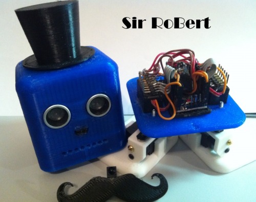
Having built TED the BiPed ( and NED, a 5 servo design I’ve never posted) and having watched the BoB revolution, and up until recently not having a 3D printer, I left the BoBs for others to build. Recently I decided to go ahead and print a BoB as the printer seemed to be working well with Jinx and other LMRians help. Once printed I was even considering giving it away to someone that wanted to build one. But then someone posted a link to a little bot (http://learn.adafruit.com/trinket-powered-rover) that had the STL files for a silly mustache that clips to an ultrasonic sensor.
I looked at the empty BoB shell and thought I have to see what a ‘stache looks like on him. I made a quick print of the mustache and stuck it up there and actually LOL’d. Someone else in the SB said he needed a tophat so a quick search turned up one, a not so quick print yielded a nice little hat for the BoB and he looked quite official. K120189, the BoB GoD and creator thereof, donned him “Robert” so that must be his name.
Just a note: Unlike most of my bot posts, this one really isn’t very close to “done”. Still a bit of coding I want to do once the platform is stable. Also want to add some more sensors such as light and sound and play a bit more with making him entertaining. But with the core done figured I’d post him up. Will update as new things are added to him.
Sir RoBert Brains and Senses
With Sir RoBert destined to be built, I began planning the layout, functions, etc. My obvious choice of a BoB Brain was a ProMini clone which I still love working with and am getting quite familiar with. Add the under $5 US price tag for a 328 CPU and it’s hard to beat in my opinion. Sir RoBert is fitted out with a normal ultrasonic sensor but it’s a bit more of a challenge to implement other sensors on this platform.
The normal ultrasonic sensor is obvious and useful for object avoidance but getting anything else like light dependent resistors (LDRs) etc mounted somewhere is a challenge. Additionally I really like having an infrared (IR) input on my builds to allow switching the “robotmode” variable for different features like roam, light follow, attack, wag, RC, etc. BUT I also want the build to look as appealing as possible. For the IR sensor I kept sticking it on different places around the BoB head and nothing really looked right until I stuck it above the mustache like a nose. Perfect fit in my opinion and that is where it stuck.
Getting light sensing on a BoB is a little trickier. It’s also not overly useful under my standard code on a biped that is twisting around back and forth all the time creating odd lighting patterns, but I still wanted to have the left/right light sensor features. I picked up some Radio Shack 3mm Ambient Light Sensors http://www.radioshack.com/product/index.jsp?productId=22472186 and will put them in the outer LED mouth holes for some type of light sensing. He at least needs to know which side of his face is brighter / darker and can respond. The key for sensing while moving is to only sense when his head is flat / forward which can be accomplished by a variable that is updated through the walk cycles. It could also be done with an accelerometer / Gyro / IMU solution but seems overly complicated for my needs. I haven’t added the light sensors yet but will be doing so in the near future.
Plug and Play
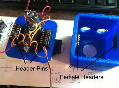
I really never realized how small the BoB head is until trying to get things stuffed into the head instead of on the outside. I really wanted everything in his head but still wanted and needed to be able to get to his brain and “inside his head” when needed. After thinking about long wires to do it, I looked a bit closer and it seemed like a set of female/mail headers would make a “plug and play” BoB head. I used two 90 degree male header pins on the bottom glued to the tops of the hip servos and glued the matching female headers on the inside sides of the head. To help line things up when putting the head on the base I added a couple pins that line up with the screw holes on the sides of the head.
It is now pretty easy to pull the head off, add stuff, fix stuff, etc and put him back together without a rats nest… well, too much of a rats nest at least, of wires, confusing connections, etc. Not perfect but pretty handy so far.
Pin In/Outs
Connected to head
2
3
4 Sonar In/Out (Using single pin mode)
5 Ch1 Input
6 Ch2 Input
Not Connected to Head headers
7
8 Right Ankle
9 Right Hip
10 Left Hip
11 Left Ankle
12 Red LED
Connected to Head
13 Speaker
A0 IR Input
A1 (Future Left Eye/Light)
A3 (Future Right Eye/Light)
A4
Not Connected to Head
A4 Green LED
A5 Blue LED
A6
A7
Remote Robert
Thinking one evening (yeah, scary thing, I know) I thought it would be cool to be able to radio control Sir RoBert with an regular radio control car controller that I had laying around. Only a two channel so some challenges but seems it could be done. My original thought was purely a free form, Arduino in the middle, solution where RC wheel input leans left and right and throttle moves right leg / left legs in a walking pattern.
This works pretty good to me allow the steering wheel to rock Sir RoBert left and right and the throttle to move his hips back and forth. Walking is a bit of a challenge to get it coordinated but with this free form way of controlling him he can get pretty crazy acting bouncing back and forth and shuffling his hips. Rocking for a formal old man.
That will work and is still a cool way to play with the bot making him move from foot to foot and shuffle or walk around. After Input from K120189 in the SB made enlightened me to the point that the radio control could also be used to trigger the “drivemode” settings I use. I.e. throttle back and he walks forward on the standard routine, reverse backs up, right turns right, combo walks and turns. So you can really just “drive” Robert around.. albeit not very fast.
Expanding on above, I have a “drivemode” variable in my code for most all my robots. That determines for each loop if the robot is just stopped, going forward, backwards, turning in place, turning gradually, etc. That way any input can subsume another for obstacle avoidance, etc. In the RC “robotmode” case, the loop simple reads the radio receiver input and sets the mode or drives the servos in a new mode for direct access. Simple but works for me.
Filling the Head
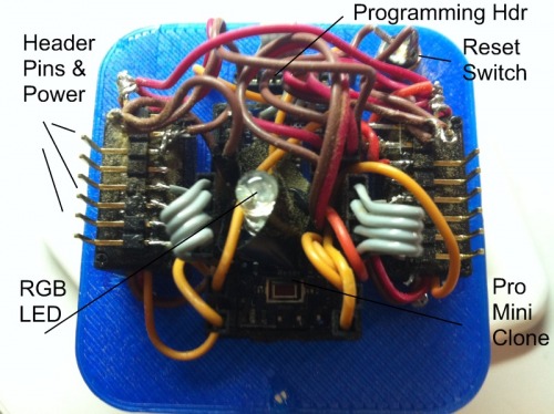
So with that wonderful plan in mind I built up the robot putting an old 75mhz RC receiver I had laying around in the very top of his head and then piled everything else in on top of that. Getting all the wiring lined out right is a challenge in such a small place but it all seemed to work out. The biggest challenge is getting power and ground runs to all the sensors, header, speaker, etc so I piggy backed the nose IR sensor off the Ultrasonic sensor which saved on connection pair. I then used the two channel connectors to the RC radio only running power in one and ground in the other removing an additional connection there.
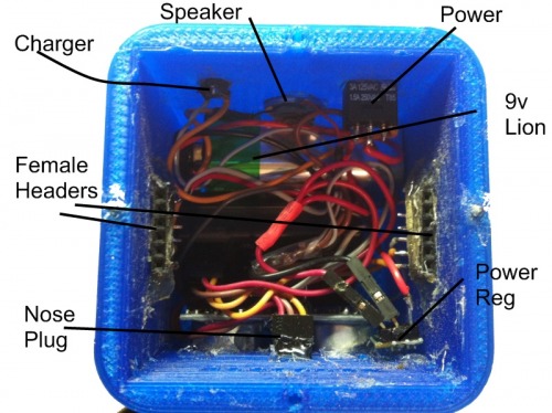
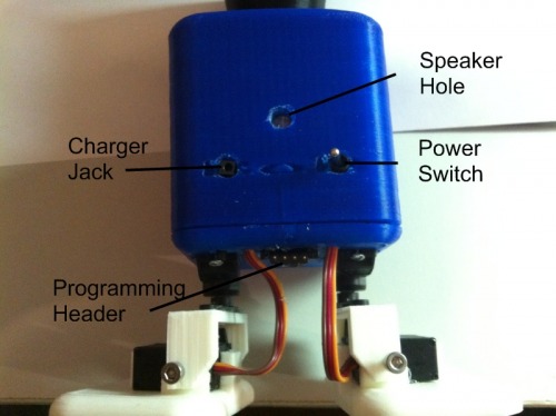
I found a tiny charger jack and power supply from an old cell phone and worked it into the back of the head, dropped in a small SPDT switch to turn him on / put in charge mode, and messed with a single RGB LED for some type of light. He really needs a bunch of 3mm LEDs but I didn’t have them so the RGB setup has to do for now.
At first I thought it would be really cool to embed a USB/TTL adapter into RoBert to allow any USB connection for programming, etc. I filled up the square hole in the back with one, set it all up and then realized I needed a USB extender cable to hook him up to the computer. Next I found that every time I plugged RoBert into the computer I had to wait for the USB to be found, re-select it sometimes, etc to program. With my lousy programming skills and the 1,000 times it takes debug/fix/re-upload my code that wasn’t going to work. I resolved it by removing the USB adapter and just extending the standard +5v/Gnd/Xmt/Rcv pin headers on the ProMini. Much easier and I can keep the same serial port for programming nearly all my bots. I did have to add an external reset button since I do not use the auto-reset wiring scheme but easy to do.
With everything installed I loaded up my standard TED code, tweaked a few servo end limits and let him try to get around. Does ok actually but still needs some limit adjustments as he will fall over pretty easily. But working so next I thought I’d try free form radio control.
Remote Gone Wrong
I added another “rcrawmode” robot mode and added the code to read the receiver controls thinking it would be pretty easy. Initially I was just powering him off the USB connection and the RC stuff worked fine. So I unplugged him, turned him on and selected RC mode with the IR remote… and he went into spasms… twisting and turning and going stupid silly. Hmm.. ok, what is going on. First I thought maybe a library was conflicting while I was reading pulse in but it worked while tethered? It finally dawned on me while looking into the head that the old 75mhz radio was mounted right next to the little Pololu 5v step up/down regulators that I use. I really figured that was it so I bypassed the regulator and powered things up from a different pack. No problems like that. Great, so my old timey radio isn’t going to work.
Next step, move to 2.4g setup. I already had an extra 2.4g receiver from my RC Truck racing days and a transmitter that could drive it so now I had to dig the old receiver from it’s mounting point underneath EVERYTHING else in the head. Only broke ONE wire doing it… surprised. Next I squeezed the new receiver in, wired it all back up and it worked!
Future Work
Sir RoBert needs some time spend on code to get him balanced out but otherwise he should be able to roam, avoid to a degree, dance with RC, play a few songs, and do the hokey pokey like most of my other bots. It’s all there, it’s just a matter of tuning settings for this particular platform but what I like about Sir RoBert is that he doesn’t look like a “robot” thrown together with scrap parts, he actually looks like a little toy guy.
Unintended Results
MaxHires and I talked a bit in the shoutbox about how bad code creates good, or at least interesting results and Sir RoBert does have some of that. There is still some issue with conflicting libraries, timers, or interrupts so the servos have the “jitters”.. BUT since Sir Robert is supposed to be old I’m just passing it off as being an “old man”.
